Before purchasing a kit, please read through this set of instructions to become familiar with the process to install a whirlpool conversion kit. Each kit will also include a printed a copy of the instruction sheet showing you how to install a whirlpool conversion kit.

Introduction
Please read these instructions to install a whirlpool conversion kit thoroughly before you begin installation.
First, gather all your necessary tools and supplies and acquaint yourself with the terminology. The instructions are based on the average tub. Not all manufacturers produce tubs the same way. Therefore, your installation may vary some as to locations of jets, suction and pump. However, the principles remain the same.
Tools & Supplies
The following tools and equipment are required to install a whirlpool conversion kit:
- 3/8” or 1/2” electric drill
- Utility knife with a new blade
- 1 3/8” hole saw (for pushbutton)
- 1 ¾” hole saw (for jet holes)
- 2 ½” hose saw (for suction hole)
- #2 Phillips screwdriver
- Tape measure
- Extension cord
- Roll of Paper Towels
- Included in Kit – PVC primer, PVC glue, Silicone caulk
- Access Panel Cover or sheet rock
Step 1: Parts
Remove all the parts from the shipping box.
After that, each box should be collapsed. Then use them for gluing and priming.
The kit to install a whirlpool conversion kit includes the following parts;
- Venturis, jet heads, jet eyeballs, and push button
- Suction head, elbow and cover
- Installation tools – string cord assistors and head tool
- Pump will have a tee, female union and stand
- 1″ hose for water, 3/8″ hose for air and 1/8″ hose for push button
- Two check valves, one for each side of the tub’s jet assembly
- Adhesive contacts and zip ties to hold each check valve
- “Y” (wye) adapters for the 3/8″ air hose
- V jet Diagram
- Plugs
- 90 degree elbow and 2 one inch “Y”s (6 and 8 jet kits only). Each “Y” is put between the last two jets near pump on each side (See Diagram)
Step 2: Priming PVC Parts
First, open can of primer and remove the dauber. Then, tap the dauber stem on the rim of the can to remove any excess primer. Now swab the insides of all the fittings that will accept the hose. Next, prime the outside of the PLUGS and the outside of the PUMP-T on the end that is the largest.
Tip: Don’t let the primer puddle in the fittings
Caution: Don’t let glue or primer get on any part of the union nuts.
Part 3: Suction Location
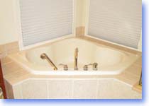
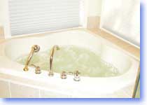
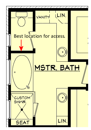
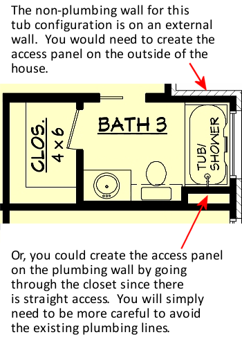
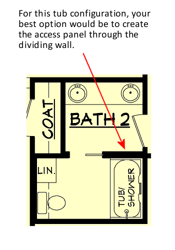
First, determine the location where you will be able to access the inside of the tub (preferably on the backrest side). If the only access option is on the plumbing side of the tub, you will have to be more careful of obstructions including the overflow tube and water supply lines.
The access location is usually through an adjoining room, closet, vanity or toilet area in a separate room. If all walls surrounding the tub are exterior walls of the house, you will have to gain access from outside of the house.
See diagrams below for sample locations.
After that, cut out a 16”x16” opening (or bigger depending on the size of the access panel you plan to install) into the location you selected for access inside the tub.
Then, locate position for suction assembly hole (2” from bottom of tub and within 2 ½ feet of pump).
Tip:
Place the suction cover (with the multiple holes) on the inside wall of the tub. Move it down as low as possible but only to where it lays flat. Mark a spot with a pencil at the top of the suction cover. Remove cover and measure 2 inches straight down. Mark this spot where you will place the guide bit of the 2 1/2 inch hole saw.
See Instruction #10 for pump placement.
Part 4: Placing the Jets
Determine where the jets will be placed. This is a matter of personal preference. We advise placing them at your ankles, knee and hips.
Caution: Be sure the middle (knee) jet hole and the back (hip) jet hole are higher than the suction hole in order that the suction hose can meet the pump without obstruction.
KEEP IN MIND:
- The height of the jets generally should be 1” below the halfway mark between the top and the bottom of the tub. Mark these spots with a pencil.
- Caution: Avoid drilling a jet hole to close to an armrest or a corner seat in the tub. There should be at least 3 inches above the drilled hole to fit the Venturi and the air hose that is glued to the barb adapter atop the Venturi.
Part 5: Determine Location of the Push Button
This control is located on the top of the tub deck, close to the pump, and within easy reach of the access panel. Mark with pencil.
Part 6: Drill Holes
With the 2 ½” hole saw, drill the suction hole.
TIP: Lay the palm of your hand on the bottom of the tub and rest the drill on the back of your hand as a guide. This hole should be entirely on the vertical wall, slightly above the curvature at the bottom of the tub.
Put 1 ¾” hole saw in your drill. Starting from the inside, drill all the jet holes. Drill slowly and deliberately. Maintain a tight grip on the drill. After you finish drilling the jet holes, change the drill bit to the 1 3/8” bit and drill the push button hole.
Part 7: Cut Hoses
Take all measurements carefully. Measure the distance between the jet holes on one side of the tub. Measure from the right side of the hole to the left side of the next hole. Under no circumstances should you use center to center. Tape measure should remain on the surface of the tub at all times so that the measurement is accurate.
If you are not sure of the measurement, cut hose a little long and assemble the VENTURIS WITHOUT glue. Then check for proper alignment of the VENTURI to the jet holes. Adjust as needed. DO NOT GLUE VENTURIS UNTIL YOU ARE SURE THE HOSE LENGTH IS CORRECT.
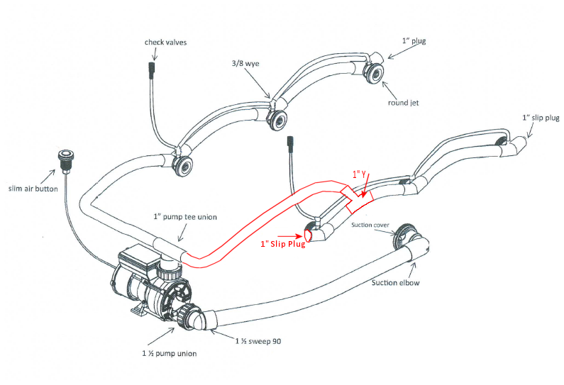
If you are installing a 6 or 8 jet system, sometimes there isn’t enough room where the pump is going to be located to make a direct hose connection to the pump. In this case, you will need to cap off the jet hole closest to the pump and use a 1″ Y between 2 jets to redirect the hose to the tee union. It should be placed 1-4″ away from the jet closest to the pump at a 45 degree angle. Repeat for the other side if needed. See Diagram
Tips:
- Dry fitting is always a good idea and is strongly recommended.
- Hose length: Measure between each hole ends and ADD 1” to the measurement (this is needed because of the slight tub curvature). Add 2” if the tub has more of a curvature.
Step 8: Glue Hoses
Prime both ends of the hose you just cut. Glue one end of the hose to the hole of the VENTURI. Glue the other end of the hose of another VENTURI. Align the Venturis before the glue sets.
Position the assembly as it will conform to the tub (either on the right side or left side – – remember that the large opening in the VENTURI is where the jets will enter). Now prime and glue the PLUGS into the VENTURI hole farthest from the pump.
Set this assembly aside and repeat for the other side.
Caution: Be sure that the VENTURI assemblies face each other so that large openings face one another.
Important: Be sure to allow enough 1″ hose to connect to the pump from the hip jet.
Prime and glue the 3/8 inch air hose to the first (ankle) VENTURI middle top hole, then extend the same hose to the barb adapter of the knee VENTURI and then to the hip VENTURI. Then extend the hose long enough to attach it to the CHECK VALVE to reach above the water line of the tub. Use the adhesive contacts and zip ties to hold each check valve in place.
Step 9: Place Hose Assembly Inside
Lasso or slip the assistors around the plastic tab inside the VENTURI and pull cord lock to tighten. Place on each VENTURI on the one side assembly.
After that, go to your access and insert the VENTURI assembly into the recesses of the tub along one side. The long end of the hose should be toward the pump.
Now retrieve the strings form inside the walls through the jet holes. A hanger or handle of a paint can or bucket will work great.
CAUTION: Do not pull too hard on the assistors because you may break the nylon insert in the venturi. If the venturi does not align properly with the hole, check your measurements.

Take one WALL FITTING/JET HEAD and liberally apply zig-zag beads of caulk behind the rim and up to the threads of the head. Also, liberally apply caulk to the rim of the VENTURI. There is no such thing as applying too much caulk here.
Thread string thru the HEAD and align HEAD with VENTURI. Hand tighten about half way (clockwise). Gently loosen the cord lock and release the string from inside the VENTURI. Do this for each HEAD and VENTURI. When completed, insert tightening tool into the HEAD and hand tighten and add a quarter to a half turn, but DO NOT OVER TIGHTEN. Repeat procedure for the other side assembly.
Step 10: Pump Placement & Suction Installation
Prime and glue the 1 ½” suction hose to the threaded suction elbow. For the 6 or 8 jet kit you may need to use the 90 degree elbow that is included in the kit to align hose with the pump.
Pump should be 1/4″ to 1/2″ higher than the lowest point of the suction hole.
This allows the pump to drain water back into the tub when the tub is emptied.
After that, locate the plastic pump stand and remove the 3 plastic cups (feet) from the template. Attach stand to pump. The pump and stand height can be adjusted by using the 1″ hose between the bottom of the stand and the feet.
Align suction elbow with hole and install suction head using silicone on threads. You can use a string to pull the threaded suction elbow up to the tub to screw in the suction head. Prime and glue the 1 1/2″ hose to the pump fittings.
Prime and glue both 1” hoses from each assembled side to the pump tee.
Then install PUSH BUTTON and connect pump air switch with air hose. Tighten the white nut on both the pump and the push button.
Finally, install your access panel or sheet rock to cover the opening you created for access.
Step 11: Clean the Tub & Insert the Eyeballs
Take a paper towel and wipe away excess caulk from the tub and around the wall fittings. Discard towel.
Then use a bathtub cleaner and clean the tub.
Then push the EYEBALLS into all the jet heads making sure you line up the prongs with the “half-moon” plastic tab inside the VENTURI. This enables the eyeball escutcheon to be turned clockwise to close the jet and counter clockwise to open the jet. All jets should be in the open position to test the whirlpool.
Allow 24 hours for the caulk to cure before using whirlpool.
Keep the Use and Care Instructions in a handy storage place for future reference.
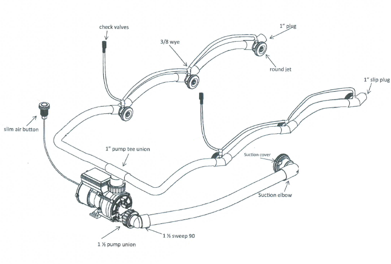
Tub Conversion Kit Diagram – Standard
Tub Conversion Kit Diagram – Using the “Y” Configuration
Still have questions?